Pump Affinity Laws: Predicting Performance
The Affinity Laws provide an expression of the mathematical relationship between the several variables involved in the performance of a centrifugal pump. In summary, they can be used to predict the effect of changing pump operating speed and/or changes in impeller diameter. Having the ability to predict the effects of changing a pump operating speed using the affinity laws is useful in such scenarios as turning down the pump to avoid excessive system flow in when it wouldn’t necessarily be prudent or required to replace a pump in order to satisfy revised system demand. Other useful scenarios include making adjustments to facilitate new service requirements or sizing a new driver etc.
We have seen that the Affinity Laws can be used to predict the changes in pump performance with a variation in pump speed or impeller diameter. Changing either of these two parameters have a knock-on effect of changing the pump flow, head, NPSH and power curves. The Affinity Laws therefore allow the resultant consequences of speed change or change in impeller diameter to be predicted with reasonable precision. The mathematical relationships of the Affinity Laws are outlined in Table 1.
Table 1: Equations for Estimating Pump Performance with Speed Change and/or Impeller Diameter.
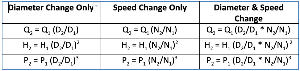
Where:
N is the shaft rotational speed.
D is the impeller diameter.
Q is the flow rate.
H is head.
P is power.
For a given pump with a fixed-speed, the pump capacity will be directly proportional to the impeller diameter. The head will be directly proportional to the square of the impeller diameter and the power required will be directly proportional to the cube of the impeller diameter.
For a given pump with a fixed impeller diameter, the pump capacity will be directly proportional to the speed, the head will be directly proportional to the square of the speed and the power required will be directly proportional to the cube of the speed. These conditions are demonstrated by the equations outlined in Table 1.
It is also worth noting that, if a system resistance remains constant, the affinity laws predict that if the pump speed is halved, then the flow rate is halved, the pump pressure/head reduces to one quarter (half squared) and the pump power consumption reduces to one eighth (a half cubed). This therefore offers the prospect of a significant energy savings if the pump speed can be reduced – perhaps during periods of low system load. This of course may only be achievable if the system has been designed in a way that pump pressure/head can be allowed to reduce significantly under part-load conditions.
Often flow margins are necessary to allow for inaccuracies in system fluid balance and the possibility of changes to the system or system extension. Figure 1 provides an illustration of the effects of changing flow conditions and the effect on pressure/head, power etc.
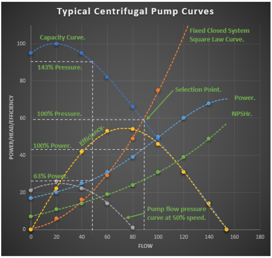
Figure 1: Typical Centrifugal Pump Curves.
Since significant energy savings can be achieved by reducing pump speed, the Affinity Laws become a particularly useful tool in determining the effect of reducing the pump operating speed on system performance.
Although the Affinity Laws can be used to predict the performance of changing pump speed or impeller diameter and indeed, the performance of geometrically similar pumps, it has generally been accepted that the application of the Affinity Laws while being reasonably accurate throughout the range of operating speeds, should be limited to around 10 to 20% for impeller diameter changes owing to the likelihood of impellers not being geometrically identical etc. A related walkthrough of applying these relationships to a specific duty point is provided in the pump selection workflow.
Applying the affinity laws in FluidFlow
This blog simply demonstrates how the affinity laws are applied within FluidFlow. Figure 1 shows an example water pipeline featuring a pump operating at a speed of 3600 RPM. The duty of the pump has been calculated as 26.97 m3/h at 25.85 m fluid with a power requirement of 3060.9 watts and an efficiency of 61.99 %.
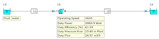
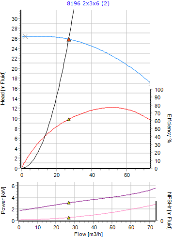
Figure 2: Pump Curves at 3600 RPM.
If the pump speed was then adjusted to 3000 RPM, we would expect the flow rate to reduce. Using the affinity laws, the software predicts the new flow rate as shown in Figure 3.
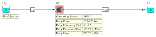
Figure 3: Pump Performance at 3000 RPM.
The new duty of the pump has been calculated as 22.32 m3/h at 17.96 m fluid with a power requirement of 1766.2 watts and an efficiency of 61.77 %. As the power required is directly proportional to the cube of the speed, we can see the dramatic reduction in pump power required.
We can see the pump node is highlighted in red indicating that there is a warning message associated with the pump. The pump has a warning message which notes that the affinity laws have been applied as a result of the speed change from 3600 to 3000 RPM. This allows the user to see instantly that the pump operating speed in the system has been changed.
Figure 4 provides an overview of the duty-point on the pump curves at this new speed of 3000 RPM.
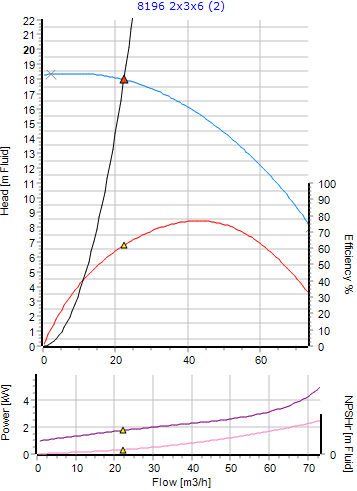
Figure 4: Pump Curves at 3000 RPM.
Apply these predictions in a complete system using the Pump Sizing and Centrifugal Pump Selection: Engineering Workflow.
Related article
See the Affinity Laws Applied in FluidFlow
A step-by-step example showing how FluidFlow applies the affinity laws when pump speed changes.