Two-Phase Flow
Simulation Software
Model two‑phase systems without guesswork. Model vapor–liquid behavior with automatic phase tracking and regime mapping.
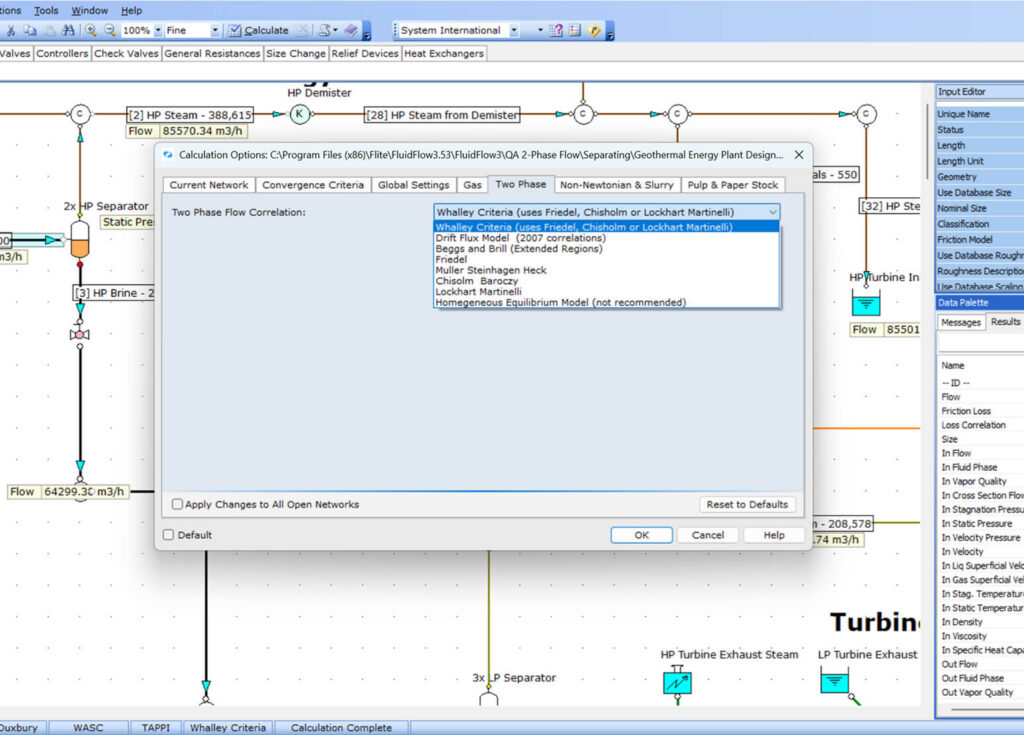
Comprehensive Correlation Library
Provides eight industry-standard correlations to calculate frictional pressure loss, including Lockhart Martinelli, Friedel, Beggs & Brill, Chisholm Baroczy
Automatic Flow Regime Mapping
Automatically generate a flow regime map (e.g., Slug, Annular, Bubbly, Stratified) for every pipe segment, allowing engineers to identify potential vibration or erosion risks.

Phase Change & Flash Calculations
Perform rigorous flash calculations to determine vapor quality changes due to pressure drops or heat transfer (e.g., steam flashing in a condensate line).

Multi-Fluid Mixing & Property Analysis
Simplify fluid mixing and transition from single-phase to multi-phase when different fluid streams converge.

Why Engineers Choose FluidFlow for Two-Phase Systems
FluidFlow’s two-phase flow simulation delivers precise vapor-liquid calculations with automatic phase tracking and comprehensive component quality analysis to accelerate design cycles and ensure optimal system performance.
Proven Two-Phase Accuracy
Achieve reliable results with marching‑solution algorithm, flash, and holdup calculations.
Intelligent Correlation Selection
Our software automatically selects optimal correlations based on fluid properties and flow conditions, eliminating guesswork.
Expert Two-Phase Support
Access guidance from engineers with deep experience in steam system design, vapor-liquid modeling, and process optimization best practices.
Industry-Specific Applications
Power Generation
Key Capabilities
Example Systems

Chemicals & Petrochemical
Application
Key Capabilities
Geothermal
Trusted Across Industries
1,000+ companies across mining, power generation, oil & gas, chemical processing, pharmaceutical, and marine industries rely on FluidFlow for two-phase flow design.
“In one case we used the software to prove to a client that a steam header system did not have the required capacity for a proposed project. This resulted in the redirection of the capital dollars and a saving of approximately $800k”
Advanced Features
Flow Regime Analysis
Automatically identify flow regimes by pipe segment, track vapor quality and liquid holdup, and model flashing and phase changes using a robust marching-solution approach.
Professional Integration
Generate clear engineering reports, import piping directly from CAD tools, and export results to standard formats for review and documentation.
System Optimization
Evaluate thermal effects, compare operating scenarios, and apply validated two-phase correlations with intelligent automatic selection or manual control.
Experience FluidFlow Today
What’s Included in your Free Trial:
Full Professional Features
Access to all simulation modules and advanced tools
14 full days
Plenty of time to test with your real projects
Sample Projects Included
Pre-built examples to get you started immediately
Live Support During Trial
Get help from our engineering team via chat and email