Liquid Flow
Simulation Software
Analyze systems faster and more accurately.
Model simple to complex liquid networks, size and evaluate pumps, identify energy savings, and improve system reliability.
Core Liquid Flow Capabilities
Eliminate guesswork in liquid transport system design.
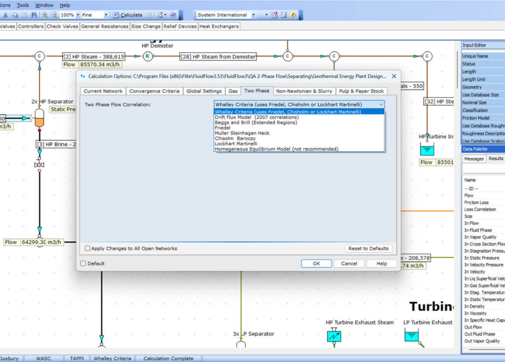
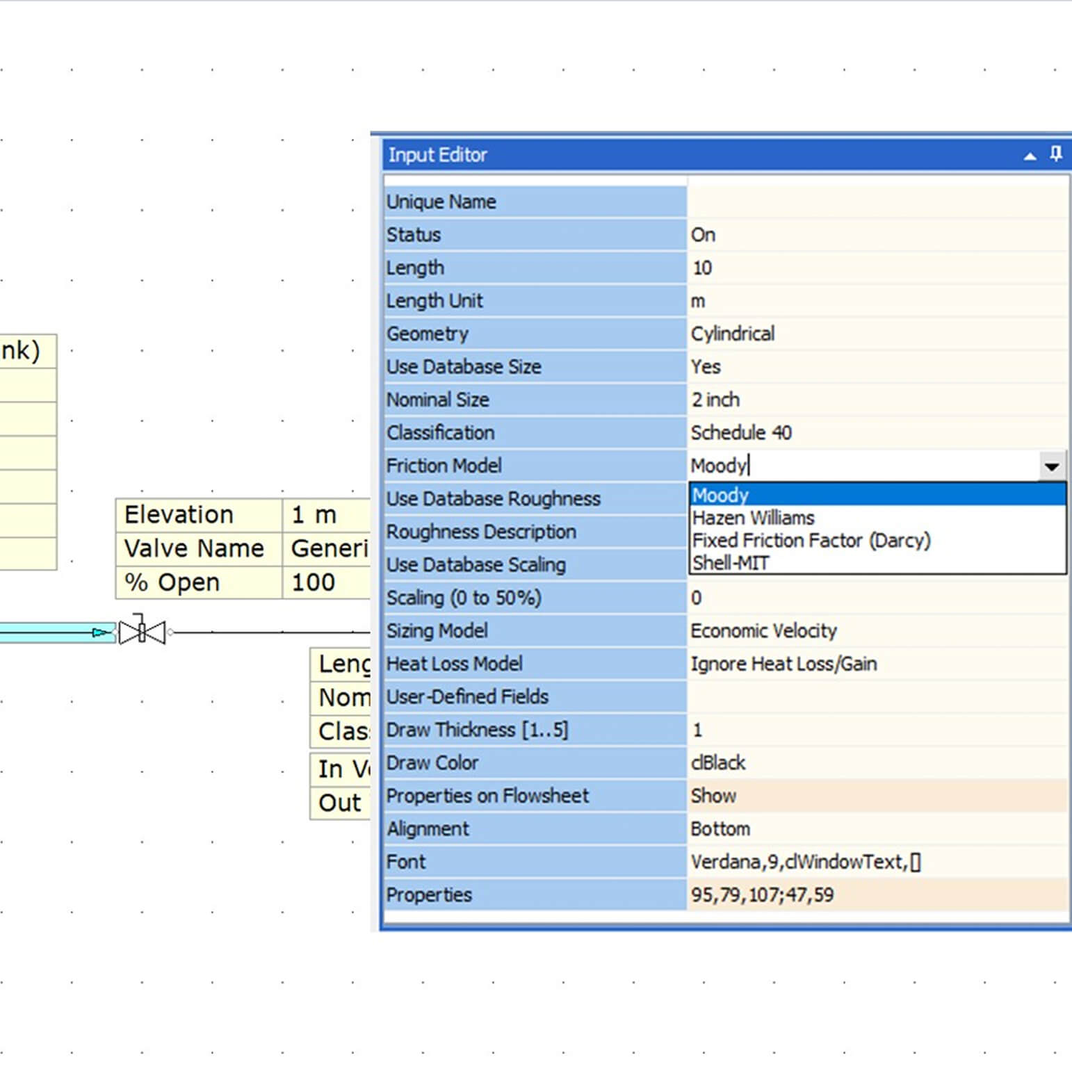
Flexible Friction Loss Methods
Choose from Darcy–Weisbach, Hazen–Williams, Shell–MIT, or fixed friction factor methods.
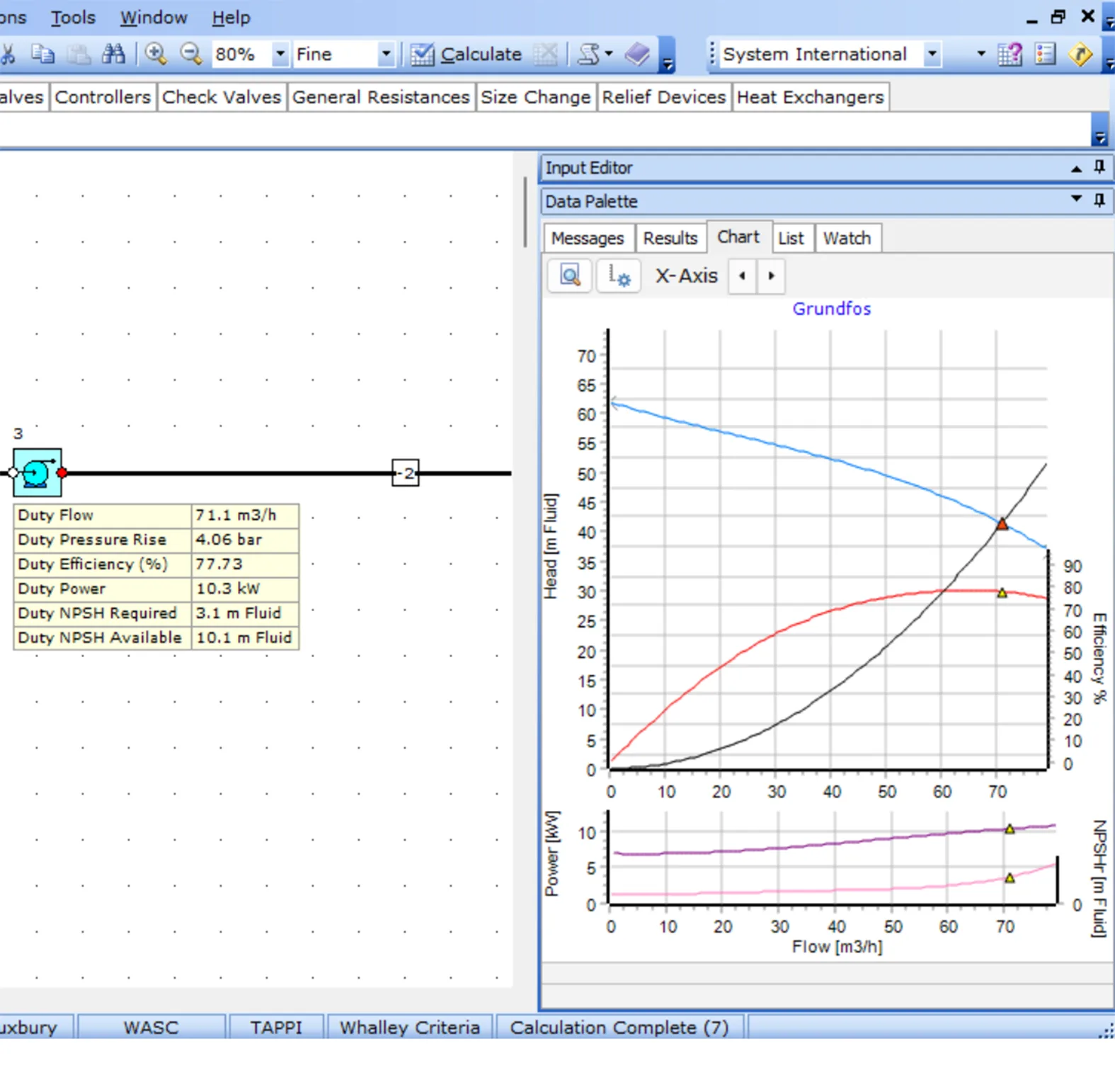
Pump Analysis
Size new pumps or evaluate manufacturer performance curves against system requirement.
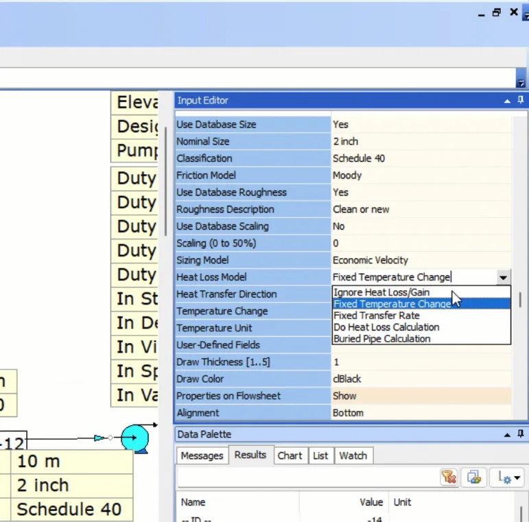
Integrated Thermal Modeling
Simulate the impact of heat loss on fluid flow behavior. Model insulated and buried piping easily.
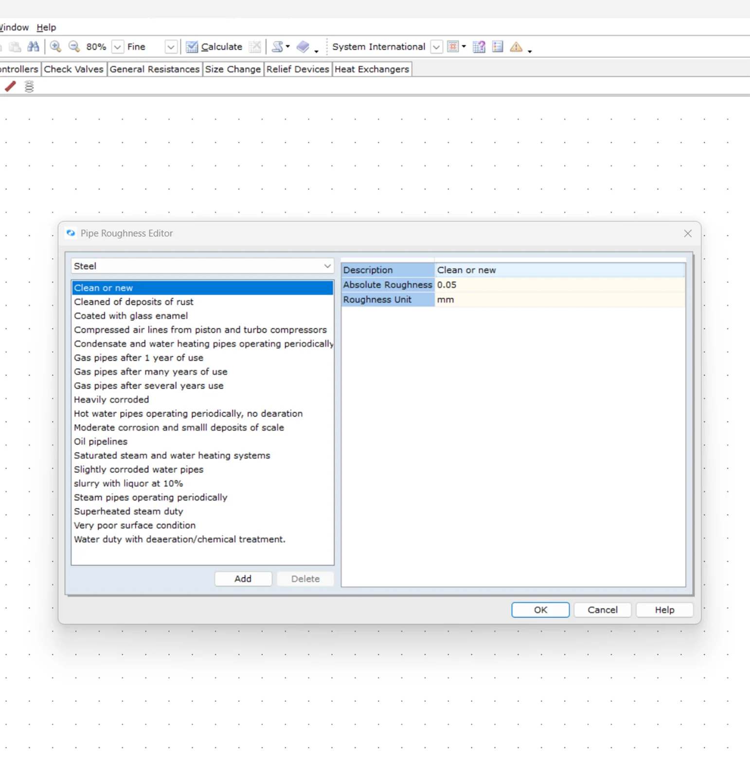
Aging Infrastructure Modeling
Account for pipe scaling, surface roughness changes, and wear deterioration.
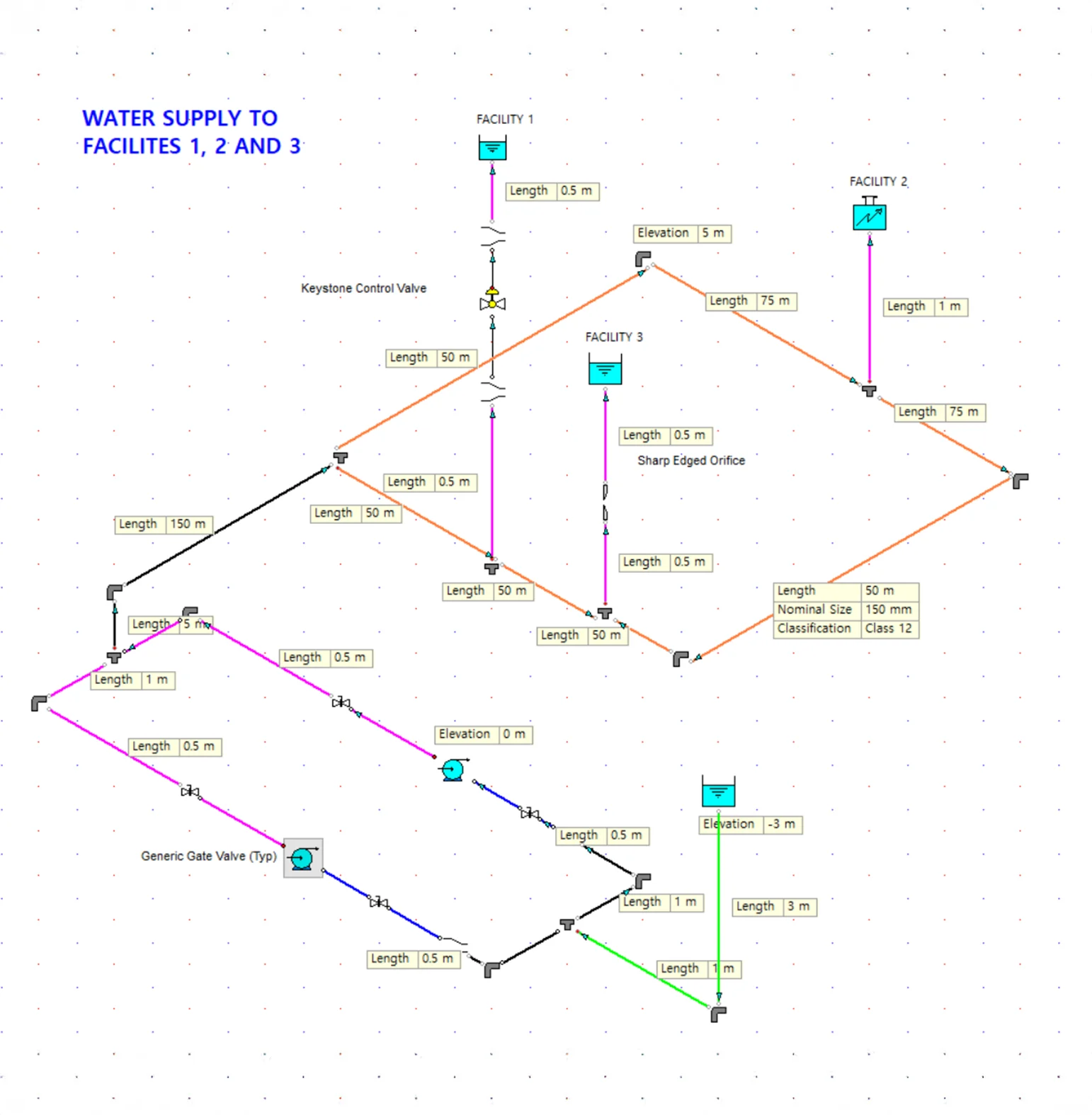
Flow Balancing
Optimize distribution across parallel and branching liquid systems.
Why Engineers Choose FluidFlow
FluidFlow provides the technical depth and practical functionality that professional engineers demand for mission-critical liquid flow applications.
Economic Pipe Sizing
using the Generaux Equation.
Proven Calculation Accuracy
with industry-standard correlations.
Superior Usability
with visual networks and fast iteration.
Industry-Specific Applications
Oil & Energy
Key Capabilities
Chemical
Key Capabilities
Example Systems
Pharmaceutical
Application
Key Capabilities
Marine
Application
Key Capabilities
Mining
Application
Key Capabilities
Example Systems
Trusted Across Industries
1,000+ companies across mining, power generation, oil & gas, chemical processing, pharmaceutical, and marine industries rely on FluidFlow for critical liquid system design.
“By using FluidFlow on this project, we had the ability to size all pipelines without pressure reducing valves as well as balance the flow through all nozzles. Balancing the flow distribution between the nozzles was easy and fast. Using FluidFlow for the design and development of this system allowed us to make significant savings on time.”
Advanced Features
System Optimization Tools
- Back‑calc analysis to eliminate manual iteration.
- Multi‑calc for rapid, comprehensive sensitivity analysis
Professional Integration
- Reporting to PDF/Excel and PCF import (Beta) integration.
- Customizable PCF Component Mapping
Experience FluidFlow Today
What’s Included in your Free Trial:
Full Professional Features
Access to all simulation modules and advanced tools
14 full days
Plenty of time to test with your real projects
Sample Projects Included
Pre-built examples to get you started immediately
Live Support During Trial
Get help from our engineering team via chat and email