Gas Flow
Simulation Software
Compressible flow made practical. Model operating conditions, reduce losses, and optimize design for gas and vapor systems.
Core Gas Flow Capabilities
Precise Computational Modeling for Gas Flow Systems
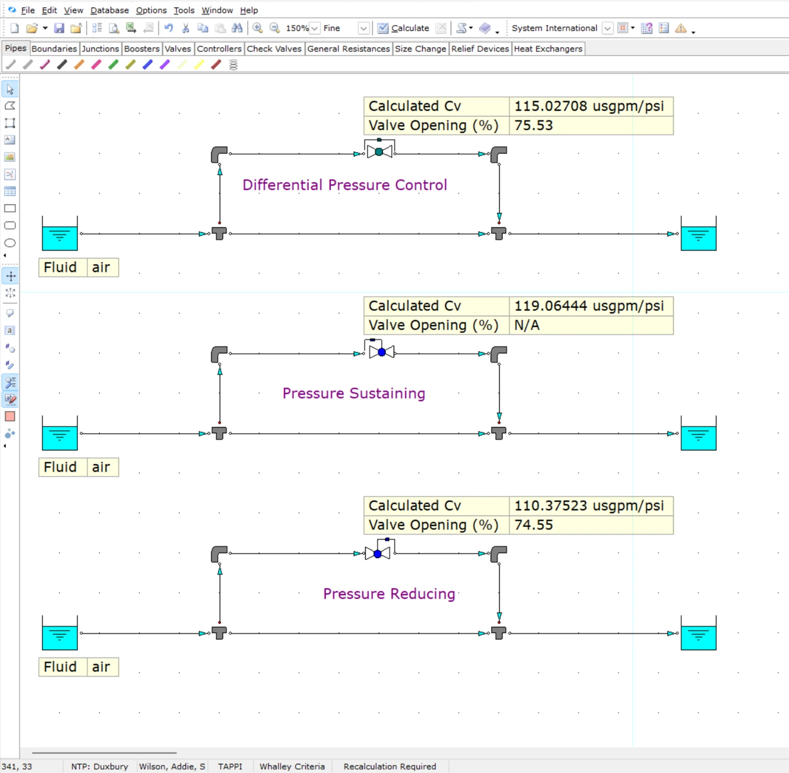
Pressure Control Valve Modeling
Model gas pressure control valves using industry‑standard sizing methods to evaluate valve performance, capacity, and stability in gas distribution systems.
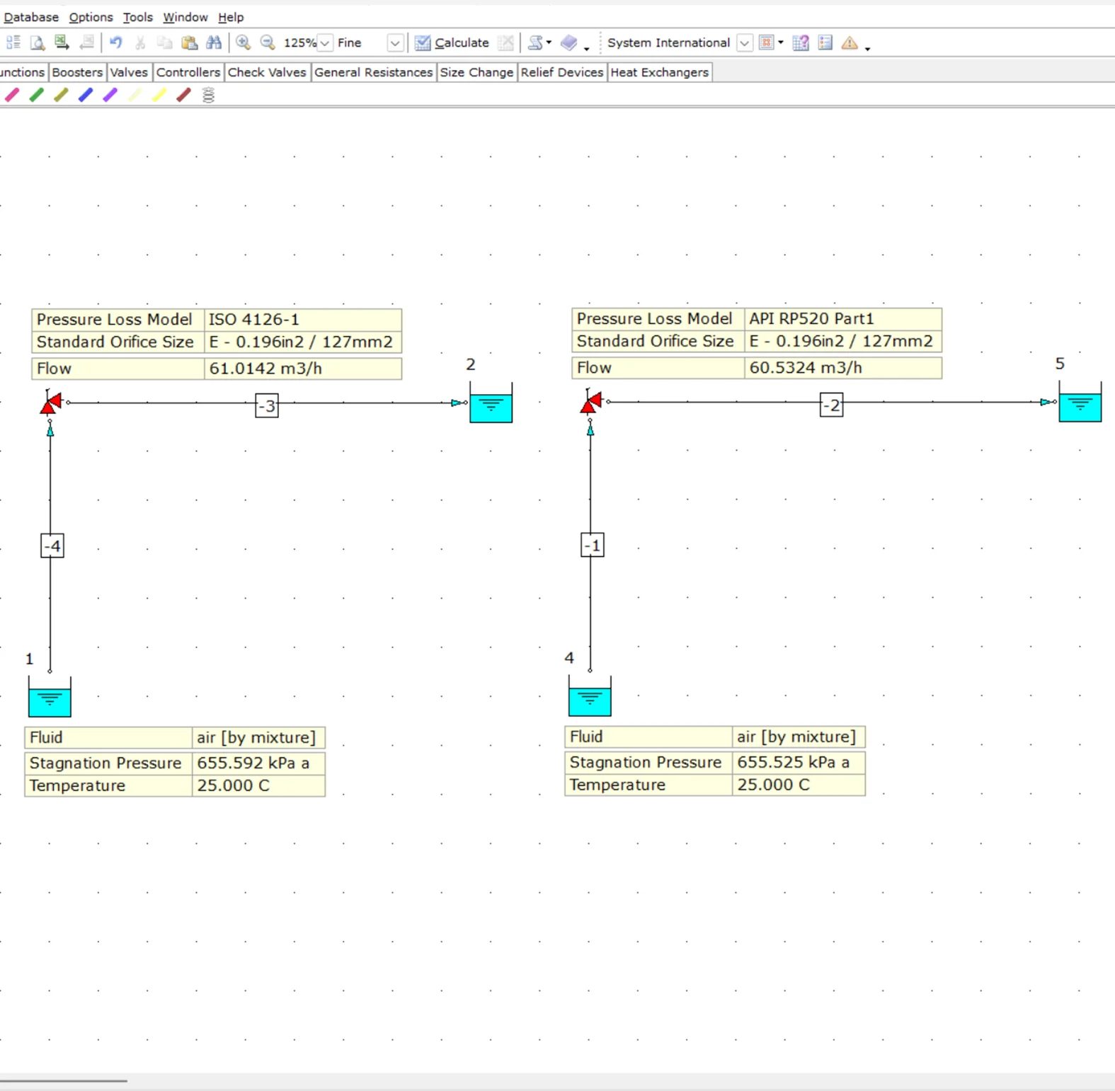
Automatic PSV Sizing
Automatically size pipes, PSVs, and orifice plates to API RP 520 Part 1 and ISO 4126‑1 standards, eliminating manual calculations and supporting compliance with industry requirements.
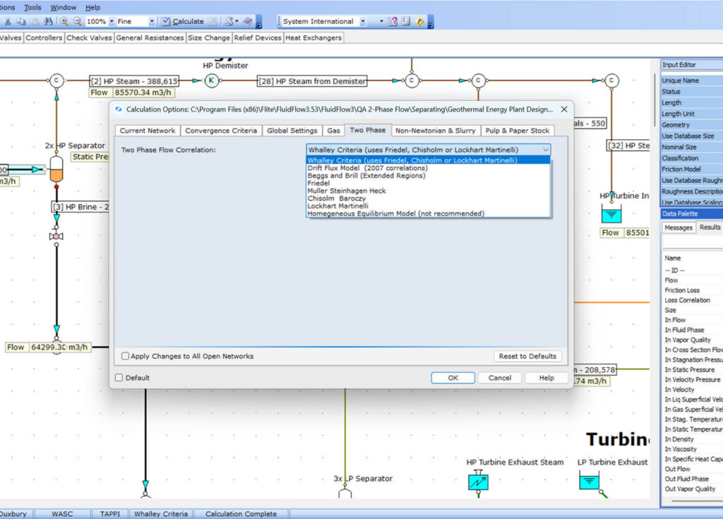
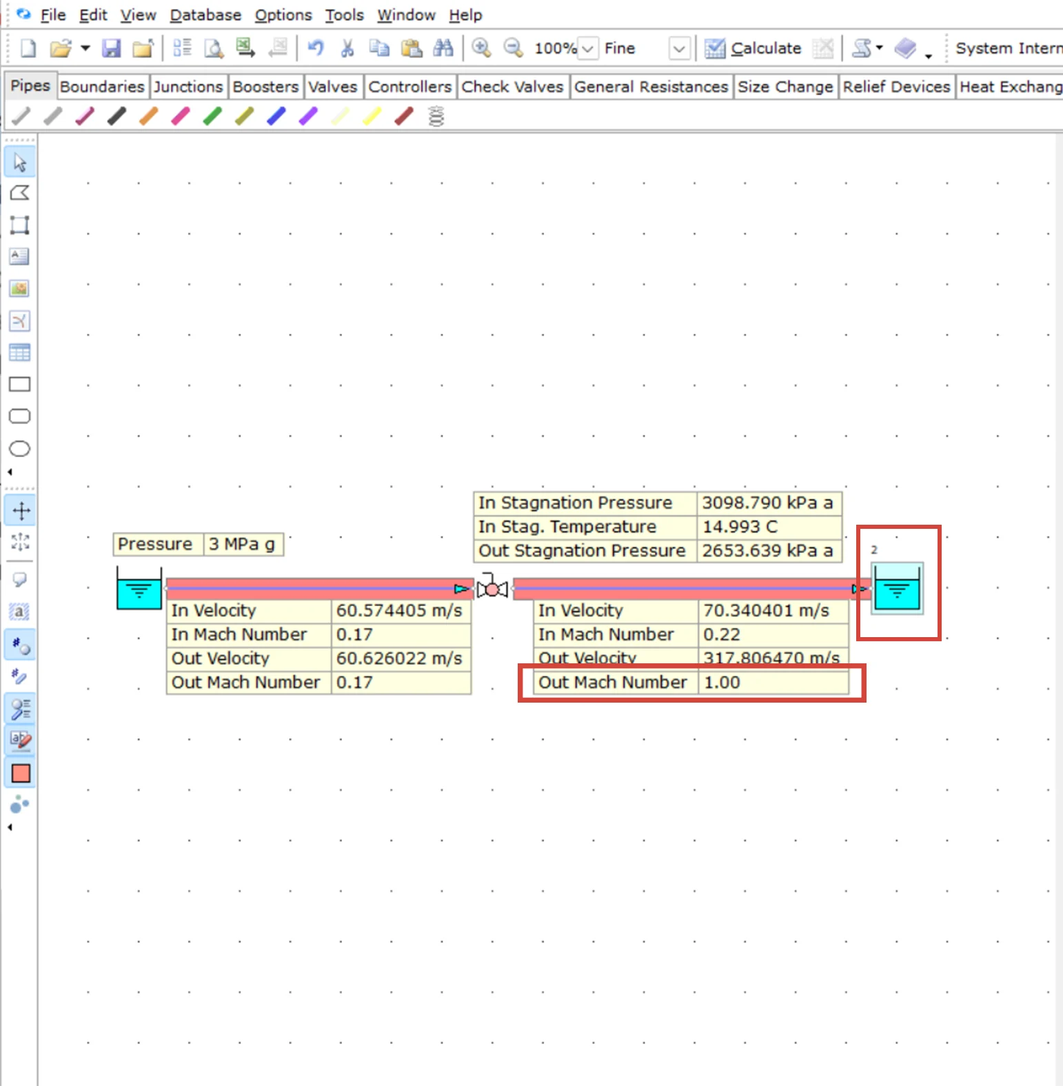
Sonic Velocity and Choked Flow Checks
Evaluate sonic velocity and choked flow conditions in gas systems so you can verify safe velocities, avoid excessive noise and vibration, and prevent capacity limitations at critical restrictions.
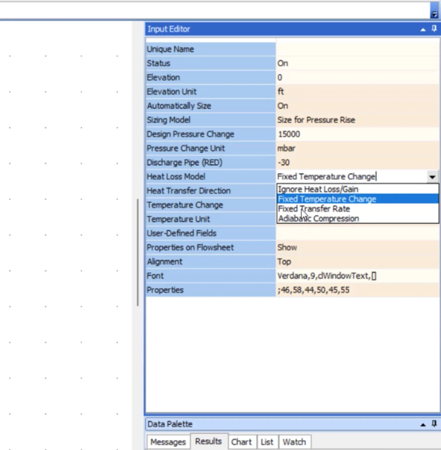
Heat Transfer Calculation
Include heat transfer in gas network simulations to account for temperature changes, thermal losses, and insulation effects, improving accuracy for sizing, pressure drop prediction, and equipment protection.
Why Engineers Choose FluidFlow
FluidFlow’s compressible flow simulation easily models gas systems and analyzes pipeline operating conditions.
Economic Pipe Sizing Using the Generaux Equation
Optimize pipe diameter by evaluating both upfront cost and lifetime energy consumption.
Accurate Pressure Loss
Compute pressure loss using conservation equations and EOS (e.g., Benedict–Webb–Rubin, Peng–Robinson, Lee–Kesler), including Joule–Thomson effects to account for temperature changes.
Clear Visualization of System Behavior
See pressures, temperatures, velocities, and demand response across the network under changing operating loads.
Industry-Specific Applications
Power Generation
Application
Key Capabilities
Oil & Gas
Application
Key Capabilities
Utilities
Application
Key Capabilities
Chemical Processing
Key Capabilities
Trusted Across Industries
1,000+ companies across mining, power generation, oil & gas, chemical processing, pharmaceutical, and marine industries rely on FluidFlow for gas compressible flow system design.
“CoMo-Industrial Engineering has measured an 80% time saving when using FluidFlow, allowing us to spend more time optimizing piping systems instead of modeling in Excel and other software.”
Advanced Features
Control Valve Sizing and Analysis
- Size and back‑calculate control valves for gas service using industry‑standard methods, checking Cv, travel, and operating range to avoid operational issues, noise, and instability.
Professional Integration
- Custom reports with pressure profiles and design summaries.
- CAD PCF import from SmartPlant 3D, CADWorx, SolidWorks. Exports to PDF/Excel.
Experience FluidFlow Today
What’s Included in your Free Trial:
Full Professional Features
Access to all simulation modules and advanced tools
14 full days
Plenty of time to test with your real projects
Sample Projects Included
Pre-built examples to get you started immediately
Live Support During Trial
Get help from our engineering team via chat and email