Flow Maldistribution in Pipe Networks: Why It Happens and How to Correct It
6 min read
A header can pass every isolated line check and still distribute flow incorrectly. One user is starved, another is overfed, and the pressure assumed to be common across the network changes once the branches begin interacting.
That is the central problem with flow maldistribution in pipe networks: branch flow is not an independent input when paths share headers or junctions. It is the result of the combined resistance, elevation, equipment characteristics, boundary conditions, and pressure balance of the connected system.
What sets the flow split in a connected pipe network?
In flow systems, pressure and flow are interdependent. Mass continuity must hold at each junction, and energy balance must hold around the connected paths. A change in one branch alters this relationship across the system, causing neighboring paths to rebalance.
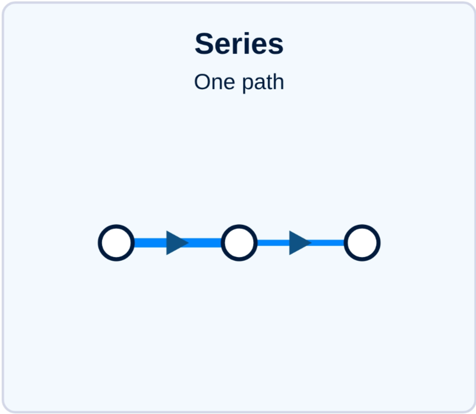
Mass Balance: The same flow passes through each element.
Pressure Balance: Total head loss is the sum of the component losses.
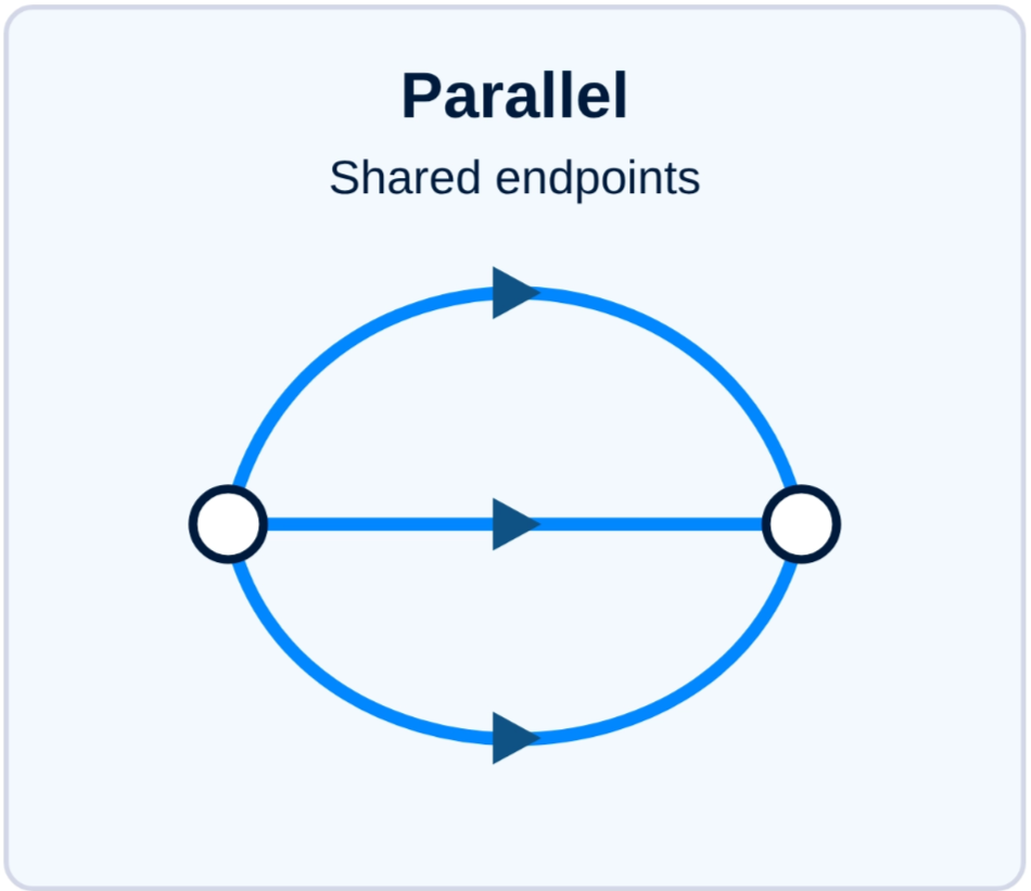
Mass Balance: Total flow is the sum of the branch flows; the split may not be equal
Pressure Balance: Flow distributes until every path between the same two nodes has the same total pressure difference.
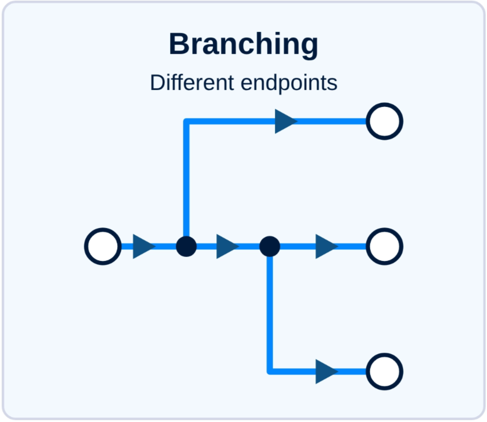
Mass Balance: Series and parallel behavior is combined; some paths do not rejoin.
Pressure Balance: Junction pressure depends on connected upstream and downstream paths. Because branch pressure differences vary, mass continuity and energy balance must be solved together.
True parallel paths share the same inlet and outlet pressure points. They therefore settle at the same pressure difference, but they do not necessarily carry the same flow. Equal nominal diameter does not establish equal total resistance when lengths, schedules, roughness, fittings, elevations, equipment, or junction geometry differ.
A branching network adds another dependency. The resistance downstream of one split affects the pressure available at later splits. Changing one diameter, valve position, or branch resistance can therefore redistribute flow through several paths.
Why isolated pressure drop calculations break down
A spreadsheet or hand calculation remains useful for checking a single path with known boundary conditions. It becomes fragile when the flow itself depends on the resistance of several connected paths.
The usual failure begins by assigning the target flow to every branch and calculating each line separately. That bypasses the question the network must answer: what flow split follows from the available pressure and installed resistance?
Effect of Pipe Size on Flow Distribution. Changing the pipe diameter alters hydraulic resistance, resulting in changes to flow distribution throughout the network.
The breakdown is most visible when:
- Several branches share a supply or return header.
- Pipe diameters, lengths, elevations, fittings, or equipment pressure drops differ.
- Tee run and branch losses vary with geometry and flow split.
- A modification to one branch changes the pressure available to the others.
- Header pressure is held constant even though it is a result of the connected demand.
A one-branch correction has the same weakness. If resistance is added to an overfed lateral, the displaced flow must go elsewhere. The rest of the network rebalances, and the complete connected model must be recalculated.
Tips for avoiding flow maldistribution
Flow maldistribution is best addressed before pipe sizes and regulating devices are fixed. The following practices reduce avoidable imbalance and make the remaining distribution easier to diagnose.
Model the complete connected network
Include common headers, branches, return paths, elevations, junctions, equipment, and boundaries in one model. Do not assign target flow to every branch when the objective is to predict uncontrolled distribution; let the connected pressure and resistance balance determine the split.
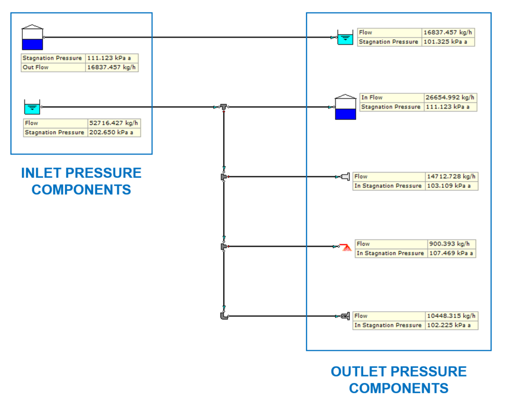
The inlet and outlet pressure boundaries that can be used in FluidFlow models.
Apply consistent pressure drop criteria
Use standard pressure drop basis for comparable flow paths. For filters, flow elements, heat exchangers, and similar equipment, apply the specified pressure drop at the corresponding design or maximum flow. For comparable control valve duties, use the same project-defined minimum pressure drop criterion.
Check tee and branch assignments
Identify each tee branch from the actual geometry rather than its visual orientation on the flowsheet. Straight and branch losses are treated differently, so an incorrect assignment can distort the calculated distribution.
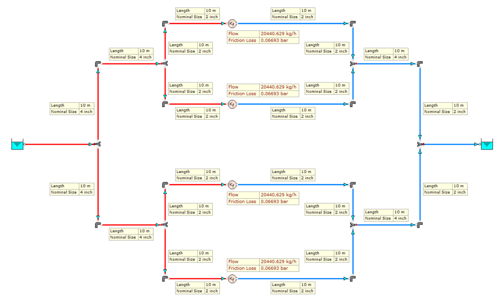
Consider a symmetric pipe route
Where the physical layout permits, use symmetric routing to keep competing paths reasonably consistent in length, fittin`gs, valves, elevation, roughness, and scaling—not diameter alone. Confirm the resulting distribution in the complete connected model rather than assuming visual symmetry produces equal flow.
Model all potential flow cases
Evaluate the credible combinations of boundary pressure, total demand, equipment lineup, fluid condition, and equipment resistance that can change the flow distribution. Compare the resulting branch flows with their targets and permitted deviations to determine the extent of maldistribution and verify whether passive balancing is sufficient or regulation is required.
Use regulation only where passive balance is insufficient
If piping changes cannot achieve the required tolerance, evaluate a flow control valve, manual balancing valve, or fixed restriction. Match the device to the operating duty and available differential pressure. Avoid incompatible fixed-flow boundaries that duplicate a control valve’s flow definition and over-constrain the network.
How does FluidFlow contribute?
FluidFlow calculates the connected pressure and flow distribution using methods appropriate to the modeled fluid, while accounting for pipe resistance, changing gas properties, and the directional losses through tees and wyes. The resulting branch flows and pressure drops show engineers where paths are over-supplied or under-supplied and which resistances are driving the imbalance. Engineers can then compare corrective options—such as revised pipe sizing, symmetric routing, branch restrictions, or flow-regulating devices—and recalculate the complete network to determine which approach meets the required flow tolerance.
The solver reports the resulting flows, pressures, pressure drops, velocities, and component behavior.
What the hydraulic model does not settle
The model calculates the flow split implied by the network as entered. It does not determine whether that split is acceptable or select the final hardware.
The result is only as good as the inputs. Incorrect lengths, clean-pipe roughness applied to a scaled line, mixed elevation datums, unsupported equipment allowances, or fluid properties that do not match the operating condition can all change the calculated distribution, even when the numerical solution closes.
In addition, the engineer remains responsible for selecting the most practical measures to prevent or correct flow maldistribution.
knowledge base
Check the junctions in your model.
The Tee Junction Flow Distribution workflow walks through branch identification, boundary conditions, and reviewing the calculated split.
Frequently asked questions
Why do equal parallel pipes sometimes carry different flows?
Equal nominal size does not establish equal total resistance. Length, schedule and inside diameter, roughness, fittings, elevation, equipment, tee geometry, and boundary conditions may differ. Confirm the actual path inputs and solve the connected network before treating the split as a control problem.
Should every branch be assigned its target flow?
Not when the purpose is to predict uncontrolled distribution. Fixing every branch flow can remove the pressure-balance problem or over-constrain the network. Define boundaries that represent the system, let the solver calculate the split, and then compare the result with engineer-defined targets.
Can changing one branch affect the rest of the network?
Yes. A change in one path alters the pressure balance at common junctions and headers, so flow redistributes through other paths. Recalculate the complete connected model after every modification rather than checking only the edited branch.
When should an orifice be used instead of a balancing valve?
Use a fixed restriction only when the duty and required distribution are sufficiently stable and the lack of adjustability is acceptable. A balancing valve is more suitable when commissioning adjustment is expected. The final selection remains an engineering and vendor decision.
FLUIDFLOW FREE BASIC TRAINING
Apply the method to your own system
Start with Free Basic Training and learn how to build and review a connected pipe-network model.