Designing Compressed Air Systems
13 min read
Inadequate or poorly designed compressed air distribution systems can lead to low productivity, poor air tool performance and perhaps more importantly, high energy bills. In order for a compressed air system to operate properly and cost effectively, it should be carefully designed to meet the needs of your applications. As part of the design process, there are six items which should be considered and factored into the final system design to give optimum results at maximum efficiency. The six items include demand, compressed air quality, supply, storage, distribution and control or management and all six must work together for the system to achieve top performance levels. The following discussion considers a number of these items.
Design your compressed air system in FluidFlow — pressure drop, pipe sizing, compressor sizing. Free license.
1) Compressed Air Demand
To determine the demand for new systems, the operating pressure requirements and duty cycle of individual equipment should be considered. Compressed air consumers are rated by the manufacturer for optimum performance at a certain pressure and air flow rate. To design a system that delivers uniform pressure, it is necessary to ensure all tools and equipment work efficiently within a narrow pressure range. However, if this is not achievable, the system can be designed to operate at a higher pressure and user regulators to reduce the pressure as required. A booster can also be added to increase pressure for any specific applications requiring higher pressures. One final option available it to design two separate compressed air systems operating at different pressures. Leakage and artificial demand can often represent a significant amount of the system overall demand. All compressed air systems exhibit leaks and leakage can be measured in a number of ways while no pneumatic equipment is in use; measured using the loaded running time of a compressor, timing the pressure drop of the receive tank while all compressors are off or
measuring leakage at the point of use. Compressed air system demand can also include artificial demand caused by excess system pressure that doesn’t increase productivity. Artificial demand can be reduced significantly by installing a regulator at the point of use of a flow controller at the beginning of the distribution network.
2) Compressed Air Quality
The quality of compressed air is determined by measuring three main contaminants which include water vapor content as measured by pressure dew point temperature, oil content as measured by concentration and finally, solid particles as measured by the concentration of by their size. The level of contamination is influenced by the type of compressor, dryer, filtration and other related components. It’s no surprise then that the higher the air quality required, the more expensive the equipment. The International Standard document ISO-8573-1 provides a classification system for the main contaminants of a compressed air system and identifies how other contaminants can be identified in addition to the classification system.
Compressed air for power-tool usage, sand blasting, pneumatic pumps etc is a relatively low-grade quality where water, oil or solid particles in the air are more of an annoyance than a major concern.
Compressed air for instrumentation is a higher quality which is used in more sensitive areas where water or particulates could contribute to significant quality issues in the process. Paint spraying and powder coating are good examples of such a process where contaminants will ultimately affect final product quality. This classification of compressed air would be filtered for solids particles and oil and dried to a higher standard to that of compressed air for say, power-tools.
Process air is often used in food or drug production. Compressed air for use under these circumstances would need to be completely oil-free with almost negligible water vapor.
Higher quality compressed air is used in hospitals or for diving applications where the air must be of a quality suitable for safe breathing.
3) Compressed Air Supply
The compressed air supply must match the compressed air demand. If the supply, storage, or distribution system are not optimized. Excessive pressure fluctuations can occur resulting in increased operating costs and reduced productivity.
Many compressors are controlled by the line pressure. An increase in demand results in a drop in line pressure which is then rectified by an increase in the output of the compressor(s). A rise in line pressure, therefore, indicates a reduction in downstream demand which causes a reduction in compressor output. There are various forms of compressor control which can be utilized to manage such system operating conditions.
Single compressor installations are generally more suited to smaller compressed air installation where the compressor may often run at full capacity. Multiple compressors installations can offer many advantages such as; an ability to adjust to changing usage patterns, provide flexibility, floor space flexibility, can be centralised or de-centralised and of course, by their nature offer a backup facility in the event of plant failure.
4) Compressed Air Storage
The provision of sufficient storage is vital and represents available energy that can be utilized and replenished as required and at any time. The air receiver tank generally provides the bulk of the total storage capacity. In some cases, the compressor controls depend on storage to limit maximum cycling frequency when the demand is below 100% of supply. A correctly sized tank will prevent excessive cycling.
Correctly sized receiver tanks can also provide sufficient storage capacity for any peaks in demand. During peaks demand periods, a poorly designed system can experience a drop in pressure as air in excess of system capacity is drawn from the system. As not all compressors in a multi-compressor system remain online at all times, the actual air supply at any time can be less than the total system capacity. During the time required to bring additional compressors online, the stored compressed air can be used to prevent any pressure drop in the system. The quantity of stored capacity needed is dependent on the amount of excess demand in cubic feet, available pressure differential between the compressor station and demand point, compressor start-up time as well as the time available to replenish the stored compressed air.
The installation of a flow controller downstream of the receiver tank is essential for providing additional compressed air when needed without downstream pressure fluctuations. The flow controller works life a precision regulator, increasing or reducing flow to maintain constant line pressure. It also provides the necessary pressure differential between the receiver tank and the system to create storage without changing system pressure downstream.
5) Compressed Air Distribution
An ideal distribution system provides a sufficient supply of compressed air to all demand points at the required pressure. Inadequate or poorly designed compressed air distribution systems can lead to low productivity, poor equipment performance and high energy bills. When designing a compressed air system, it is therefore good practice to consider the factors which help improve the efficiency and reliability of the compressors and ancillary equipment, minimise leakage and pressure drops and improve compressor life-cycle cost.
In general, there are three demands imposed on a compressed air distribution system; low-pressure drop between the compressor and most remote demand point, minimum leakage from the distribution pipework and efficient condensate separation if a compressed air dryer is not included in the system.
The compressed air pipe routing, design and dimensions are important factors for the efficiency, reliability and cost of compressed air production. Occasionally, a large pressure drop in the piping system is compensated by adjusting or increasing the working pressure of the compressor from for example, 7 bar to 8 bar. This results in inferior compressed air economy. Furthermore, when compressed air consumption is reduced, the pressure drop is also reduced and so the pressure at the demand point consequently rises above the allowed level. This therefore is not a recommended operating strategy.
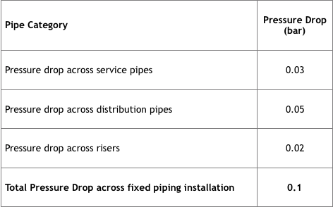
In general, fixed compressed air distribution systems should be sized such that the pressure drop in the pipes does not exceed 0.1 bar (10,000 Pascals or 1.45 psi) between the compressor and most remote demand point. The pressure drop arising from flexible hoses, couplings and fittings should also be included in the pressure drop calculation. However, if possible, in an attempt to reduce pressure losses, the number of bends, valves, fittings or flow obstructions should be kept to a minimum.
A useful approach is to design a ring main or looped piping system to serve the space where the compressed air consumption will take place. This is an effective way to minimise pressure drop in a system. Branch pipe connections are then run from the loop to serve the various demand points. This helps provide for a uniform compressed air supply as the air distributed to the demand point from two directions.
The design of a ring main system is a recommended approach however, may not be entirely suitable in scenarios where there are large compressed air consumers located at a much greater distance from the compressor installation. It is recommended that a separate compressed air main should be routed under these circumstances to serve this equipment.
Compressed air piping system can generally be grouped into four main parts; risers, distribution pipes, service pipes and compressed air fittings. The risers transport the compressed air from the compressors to the consumption zones, the distribution pies split the air across the distribution zone and the service pipes route the air from the distribution pipes to the working areas/final demand points.
At design stage, the starting point is generally to obtain a diagram indicating the location of all compressed air equipment and an equipment list detailing all compressed air consumers. The compressor plant should be in a centralized location in close proximity to all relevant applications and processes in order to minimize the length of piping between the compressor station and the consumers. The consumers should ideally be grouped in a logical manner and supplied from the same pipe.
The location of the compressor must also give consideration to the quality of intake air, ideally clean, dry and cool. The compressors should be positioned clear of any potential steam, chemical vapors, engine exhaust and dust.
The pressure developed by the compressor plant can generally never by fully utilized as a result of pressure losses occurring in the system from pipework and fittings. When designing and sizing the various piping zones of the system, the following rule of thumb can be used for pipe losses.
The length of the pipes required for the system can be scaled off the design plan and section drawings for the building/facility. The pipes can then be sized using relevant formulae and/or pipe sizing tables or nomograms. The flow rate, pressure, allowed pressure drop and length of pipe usually must be known in order to correctly size the pipework. When sizing the pipework, the equivalent length for each pipe section is estimated in an attempt to take into account the losses from fittings. It is also often necessary to design and calculated the service pipes, distribution pipes and riser pipes separately, particularly for larger installations.
It is also worth remembering that, horizontal pipe installations should have a slope of around 1 to 2 % toward the point of consumption to aid the transfer of condensate to the predetermined drain points. Note, some would argue that the need to slope the pipework is no longer required when a correctly sized air dryer is installed however, the cost is minimal/negligible and offers added protection in the event of an air dryer failure.
The use of an appropriate software tool helps overcome the difficulties with designing these systems by hand. Using tables, nomograms etc can be time-consuming and occasionally, error prone. Applying the equivalent length approach in a hand calculation also produces a lower level of accuracy by comparison to a software-based solution. FluidFlow helps with the design of such systems and allows the designer to consider dynamic type operating scenarios with fluctuating demand etc.
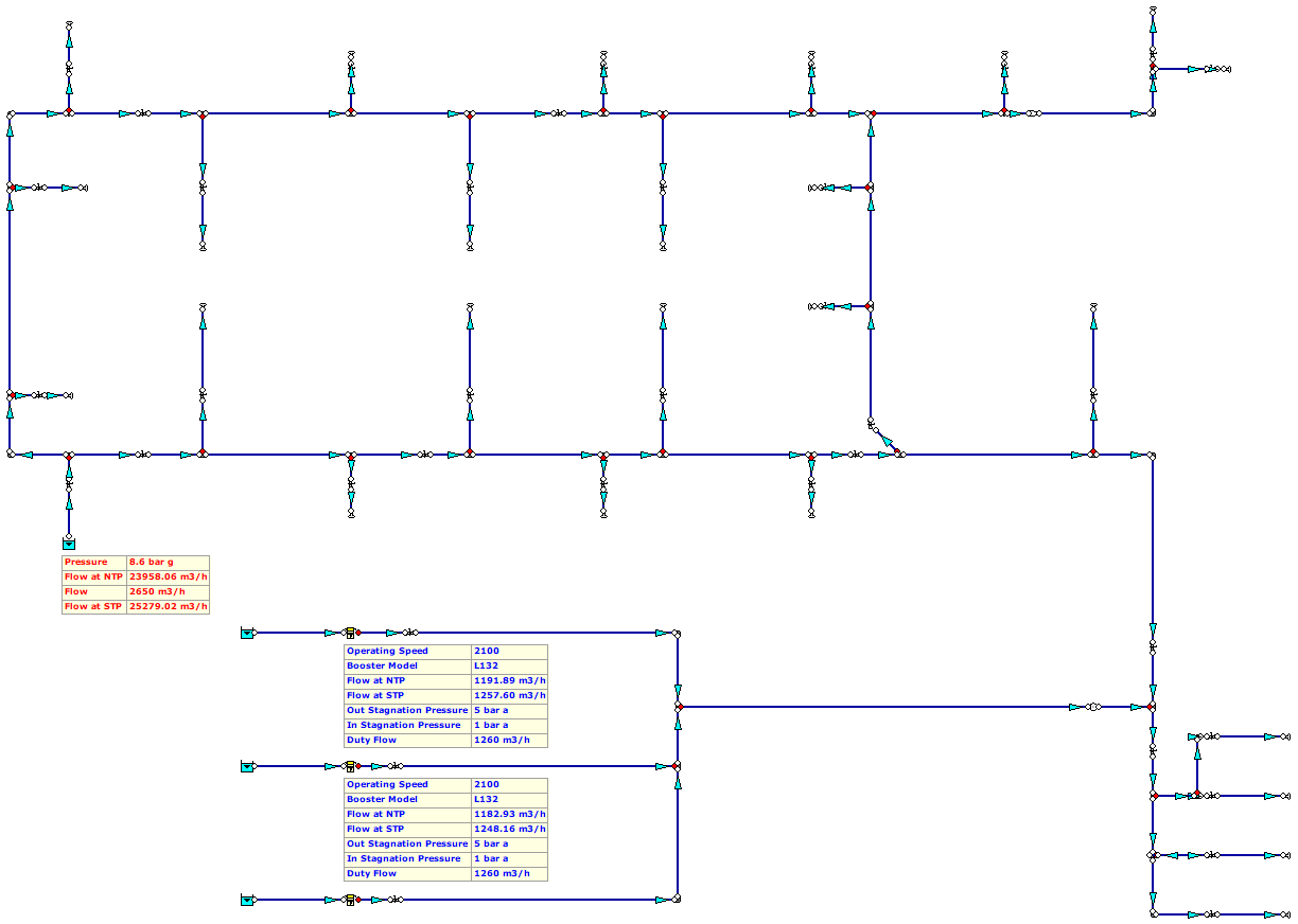
Figure 1: Compressed Air System Model.
Compressed Air System Performance
Tests and experiments have shown that for every 1 bar in pressure drop across the system, the resulting power consumption is increased by circa 6 – 7 % (plus the additional cost of unregulated users). Accordingly, the distribution network can have a profound influence on the system performance. There are a number of steps which can be taken to optimise the air distribution system.
1. Pressure Drops and Line Improvements.
As outlined previously, a ring main is generally the most efficient type of distribution layout. Air mains are usually sized on velocity and a velocity level of 6 to 9 m/s is common as this is sufficiently low to prevent excessive pressure drop and should also allow reasonable water separation. The local feeding mains can flow up to around 15 m/s. However, in order to prevent adverse pressure drops, the flow velocity in the main header sections should not exceed circa. 6 m/s.
It is best to replace any tee connections for directional angle entry connections or swept tees. Turbulence caused by a 90o tee connection can cause pressure drops resulting in back pressure sending a false “unload signal” to the compressors which can potentially cause excessive cycling of the compressor.
Incorrect pipe sizing and restrictions are a major source of pressure losses in the system. Losses in the interconnecting distribution pipework between the compressor and the header distribution piping are commonplace however, the losses along these lines should be kept to a minimum.
Interconnecting piping between compressors or systems often require close attention. It is vital that they are carefully designed to avoid sending back any false signals to the compressor.
2. Leak Detection
Leaks in compressed air systems are a regular feature. The energy requirements served by compressed air systems are intermittent in nature, however leaks are constant and surprisingly, potentially significant. The monetary cost of leaks can be quite startling and perhaps a little eye watering.
For instance, one 4mm hole in a compressed air distribution pipe can cost €2,005 per annum on a typical compressed air system operating throughout the year and at 8 bar.
In addition to the monetary cost, leaks can cause significant pressure drops resulting in excessive compressor cycling. In an attempt to reduce the pressure loss in a system where excessive leakage is an issue, operators occasionally increase the system discharge pressure. However, this has the effect of exacerbating the problem by increasing the leakage rate and create more leaks in the future.
It is not uncommon for leakage rates to be around 20 – 30%. Leaks can occur at any point in the system with joints, drains, valves regulators etc being the most common sources. Fixing leaks in the most basic form can occasionally be as simple as tightening connections or applying a sealant at a strategic point. However, leaks will be found which require replacement of faulty components. It is worth noting that one of the most effective means of reducing leakage is to reduce the distribution pressure. Note, a 10% reduction in leakage would often be achieved through carrying out an appropriate leak reduction programme.
3. Dedicated Air Receivers for End Users.
In industrial applications where air pressure is subject to large fluctuations or variations, air receivers are beneficial. In these situations, the increased compressed air requirement is compensated by air from local air receivers thus minimising idling at the generation station. The receivers subsequently replenish slowly using control valves to minimise peak energy demand on the compressor station. In addition to reduced compressor cycling, air receivers provide protection for end users that require high pressure by minimising the system pressure drop off while supporting the speed of transmission response in supply.
Other useful tips with regard to compressed air system design include:
- Position one air receiver near the compressor to provide a steady source of control air, additional air cooling and moisture separation. A large storage receiver can be located downstream of the dryer and filters to act as a buffer for demand surges and controlled by a flow controller.
- Compressors should be positioned in a clean, dry, cool and well-ventilated room. Ensure there is sufficient room around the compressors and equipment for proper air flow. Manufacturer’s will often specify the minimum spacing required around compressors.
- Piping in a loop is recommended will all piping sloped to accessible drain points. Air outlets should be taken from the top of the main lines to prevent moisture entering the outlet.
- Under average conditions, every 100 cfm of air compressed to 100 psig (6.89 barg) produces approximately 20 gallons (75.7 litres) of condensate per day which needs to be treated.
- The minimum amount of storage recommended is one gallon per cfm of capacity. This should be increased to 4 to 10 gallons per cfm of capacity for systems with sharp changes in demand.
References:
- Chemical Engineering, March 2018.
- SEAI – Compressed Air Technical Guide.
- Atlas Copco Compressed Air Manual.
- Designing Your Compressed Air System – Kaeser Compressors.
knowledge base
Ready to apply this in FluidFlow?
Design your compressed air system in FluidFlow — the Gas Flow Webinar covers compressible flow setup.


