Relief Valve Sizing Software
API 520/521 | FluidFlow
Size Relief Valves to Standards, in System Context
Relief valve sizing is one of the few engineering tasks where an error has safety consequences. Get the orifice too small, and the vessel exceeds its maximum allowable working pressure. Get the inlet piping wrong and the valve chatters or fails to reseat. Get the backpressure wrong, and the valve capacity drops below what the scenario demands.
FluidFlow sizes relief valves and rupture discs to API RP 520 for gas and liquid service. The difference from a standalone calculator: FluidFlow does it inside your pipe network model. Inlet pressure drop checking and backpressure evaluation use calculated pressures from the actual piping, not assumed values from a datasheet.
The Problem: Manual Sizing Detached from the Piping
Relief valve sizing involves multiple interdependent calculations: required relief flow, set pressure, orifice area, inlet piping effects, and backpressure from the discharge system. Manual methods handle these sequentially, often in separate spreadsheets.
This creates problems:
Unit conversion errors. Relief sizing crosses between mass flow, volumetric flow, pressure units, and temperature. Every manual conversion is a chance to introduce an error in a safety-critical calculation.
Coefficient lookup mistakes. The correct discharge coefficient, backpressure correction, and capacity factor depend on the valve type, fluid state, and installation. Manual lookup and interpolation are error-prone.
Disconnect from the piping system. The pressure available at the relief valve inlet depends on the upstream piping. The effective capacity depends on the downstream backpressure. A standalone calculation uses fixed pressure values. The actual system has pressure profiles that change with flow.
No regime checking. As conditions change across the relief valve, the fluid may change state. A manual calculation sized for gas may not account for conditions that produce a different flow regime.
How FluidFlow Works
1. Define the fluid and relief conditions
Select from FluidFlow’s database of 1,283 fluids or define a custom fluid. Set the relief scenario conditions: upstream pressure, temperature, and required relief flow.
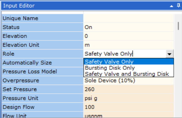
2. Configure the relief device
FluidFlow supports two device types:
| Device | Description |
|---|---|
| Relief valve | Spring-loaded or pilot-operated pressure relief |
| Rupture disc | Burst disc sized using the Resistance to Flow Method (Kr) for sharp edge, bellmouth, in-projecting, API, and liquid disc types |
FluidFlow operates in two modes:
- Auto-size on: FluidFlow determines the required orifice area based on relief conditions
- Rating mode (auto-size off): Evaluate an existing device against specific conditions
3. Set the relief valve set pressure
FluidFlow supports standard accumulation configurations:
| Configuration | Accumulation |
|---|---|
| Sole device | 10% above MAWP |
| Multiple devices | 16% above MAWP |
| Fire case | 21% above MAWP |
4. Solve in the network
FluidFlow supports multiple relief-related activities in the network model. Depending on what you are doing, the system can solve:
- Required orifice area for the relief scenario (PSV orifice sizing)
- Inlet piping pressure drop from the vessel to the valve (inlet line pressure drop check and or inlet line sizing, as applicable)
- Backpressure from the discharge piping (outlet line backpressure check and or outlet line sizing, as applicable)
- Calculated pressures at the valve inlet and outlet from the network model
- Design alerts and warnings from FluidFlow’s validation checks library
Key Capabilities
API RP 520 Sizing for Gas and Liquid
FluidFlow sizes relief valves following API RP 520 for gas and liquid service. The standard governs the calculation of required orifice area based on fluid properties, set pressure, and flowing conditions. FluidFlow automates these calculations within the network model, reducing the manual steps where errors typically occur.
Inlet Piping Pressure Drop Checking
The pressure drop between the protected vessel and the relief valve inlet affects valve performance. Excessive inlet pressure drop can cause valve chatter, reduce capacity, or prevent proper reseating. FluidFlow calculates the inlet piping pressure drop from the network model, using the actual pipe geometry, fittings, and flow conditions rather than estimated values.
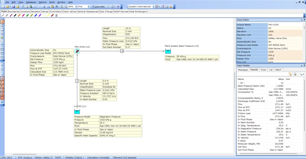
Backpressure Evaluation
Relief valve capacity depends on the backpressure in the discharge system. In conventional relief valves, superimposed backpressure reduces the effective set pressure. Built-up backpressure during relief flow reduces the pressure differential across the valve. FluidFlow evaluates backpressure from the solved discharge piping network, accounting for the actual pipe lengths, elevations, and connections to a flare header or atmospheric discharge.
Rupture Disc Sizing
FluidFlow supports rupture or bursting disc sizing using the Resistance to Flow Method (Kr).
Relief Valve Vendor Database
FluidFlow includes a default database of relief valves from several vendors. Select a valve from the database or define custom device parameters.
Why FluidFlow: System Context, Not a Standalone Calculator
A standalone relief valve calculator takes fixed inlet and outlet pressures. It returns an orifice size. What it cannot tell you:
| Standalone calculator | FluidFlow |
|---|---|
| Fixed inlet pressure | Inlet pressure from network solve (accounts for vessel to valve piping) |
| Fixed backpressure | Backpressure from solved discharge system |
| No inlet piping check | Inlet pressure drop calculated from actual piping geometry |
| No interaction with other devices | Relief valve operates within the full network model |
| Manual regime checks | FluidFlow checks flow conditions automatically |
| Separate pipe sizing | Pipe sizing in the same model |
FluidFlow integrates relief valve sizing with pipe sizing and control valve sizing, so the complete system is designed and verified in one model.
Use Cases
Gas Relief Valve Sizing
Sizing pressure safety valves for gas service per API RP 520. FluidFlow calculates the required orifice area, checks inlet piping pressure drop, and evaluates discharge backpressure within the network model. The gas module handles real-gas properties via the equation of state, so fluid density and compressibility are calculated at actual conditions.
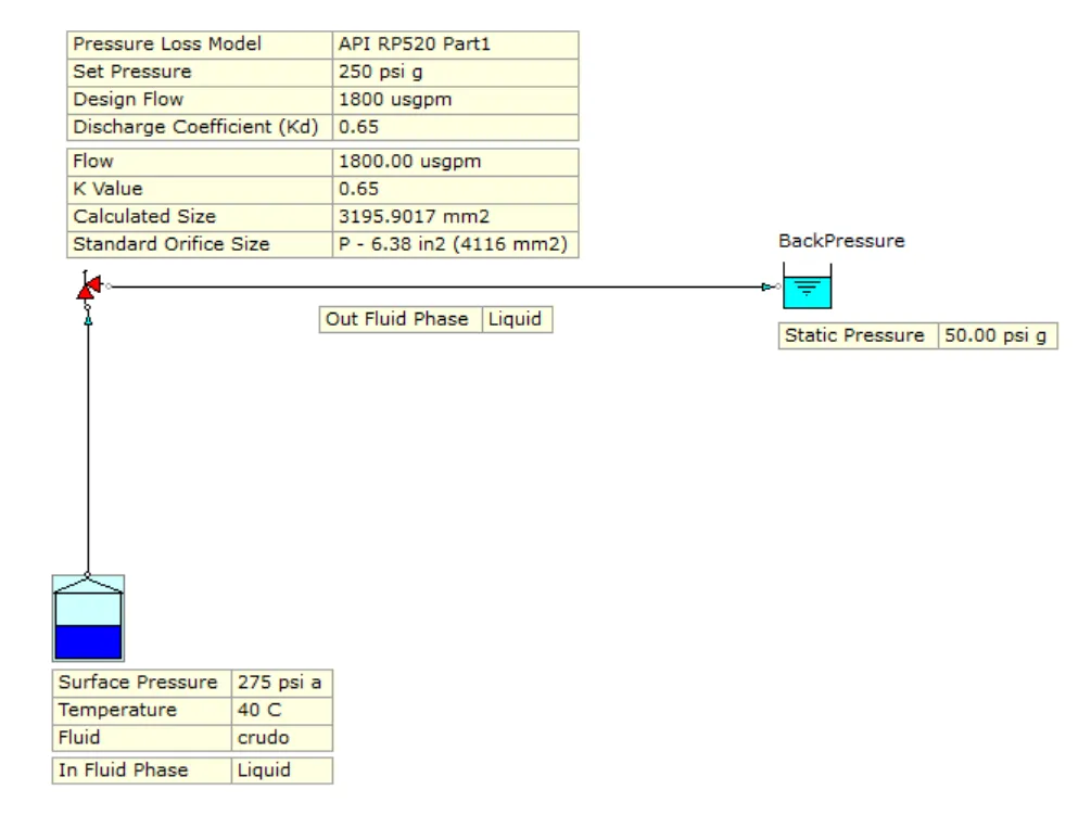
Liquid Relief Valve Sizing
Sizing relief valves for liquid overpressure scenarios per API RP 520. FluidFlow accounts for liquid incompressibility and the different sizing equations applicable to liquid service. Inlet and discharge piping effects are evaluated from the network solve.
Steam Relief Valve Sizing
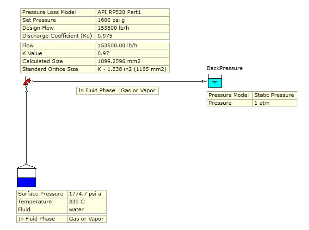
Sizing relief valves for steam service per API RP 520. FluidFlow calculates the required orifice area using steam properties from its fluid database, accounting for the specific volume and isentropic expansion behaviour of steam at relief conditions. Inlet piping pressure drop and discharge backpressure are evaluated from the network model, providing system-context verification for steam relief installations.
Two-Phase Flow Relief Valve Sizing
FluidFlow supports two-phase relief valve sizing with limitations. Where a relief scenario involves both gas and liquid phases, FluidFlow can evaluate the relief conditions within the network model. As two-phase relief methodology continues to be refined, contact FluidFlow support for guidance on specific two-phase relief scenarios and current capability boundaries.
Rupture Disc Applications
Where rupture discs are used as primary relief devices or in combination with relief valves, FluidFlow sizes the disc using the Resistance to Flow Method (Kr) and uses the network model to determine pressure conditions at the disc location.
Inlet and Discharge Piping Verification
Beyond sizing the device itself, FluidFlow evaluates the piping connected to the relief valve. Inlet piping pressure drop and discharge backpressure are calculated from the solved network, providing the context needed to verify that the installation supports proper valve operation.
Re-rating Existing Relief Valves
When process conditions change — increased throughput, modified operating pressure, revised piping layout, or a new relief scenario — existing relief valves must be verified against the new loads. FluidFlow supports this during auto-size off where actual relief valve performance data is used for modeling flow behavior in the system to evaluate adequacy of the relief valve to handle the new load and check if inlet piping pressure drop and backpressure are within acceptable levels.
Frequently Asked Questions
FluidFlow supports API RP 520 for gas and liquid relief sizing. ISO 4126-1 is also available as a standard option within the software.
Yes. In auto-size mode, FluidFlow determines the required orifice area based on the relief conditions, fluid properties, and set pressure configuration. In rating mode (auto-size off), you can evaluate an existing valve against specific conditions to confirm it meets the relief requirement.
FluidFlow calculates the pressure drop between the protected vessel and the relief valve inlet using the actual pipe geometry, fittings, and flow conditions from the network model. This replaces manual estimation with a calculated value that reflects the real installation.
Yes. FluidFlow sizes rupture and bursting discs using the **Resistance to Flow Method (Kr)**. Select the disc type and FluidFlow applies the appropriate Kr value based on the disc configuration.
*Note:* FluidFlow does **not** size rupture discs using the Coefficient of Discharge Method (Kd).
Yes. FluidFlow supports two-phase relief valve sizing with limitations. Contact FluidFlow support for guidance on specific two-phase relief scenarios and current capability boundaries.
Start Sizing Relief Valves in Your System
Download FluidFlow today
Relief valve sizing is a safety-critical calculation that belongs in the context of your pipe network. Get full access to all FluidFlow modules.
Questions?
Contact [email protected] or call +44 28 7127 9227.