Pumps in Parallel & Series: Configuration Guide
11 min read
Why Multi-Pump Configurations Matter
A single pump rarely satisfies every operating condition a piping system will encounter. Flow demand changes with process load, elevation differences impose head requirements that one pump cannot meet alone, and maintenance windows demand redundancy. Configuring pumps in series or parallel is the standard engineering response — but the choice between the two, and the details of implementation, determine whether a system runs efficiently or creates chronic operational problems.
Model your pump configuration in FluidFlow. Verify NPSH, combined curves and trip scenarios before the order goes out.
This article walks through the key questions every engineer should answer before committing to a multi-pump arrangement, from system curve analysis through NPSH verification to control strategy.
Series vs. Parallel: Which Does What?
The distinction is straightforward in principle. Pumps in series add their heads at a common flow rate — the fluid passes through one pump, then the next, gaining pressure at each stage. Pumps in parallel add their flow rates at a common head — each pump draws from a shared suction header and discharges into a common line, increasing total throughput without a proportional increase in head.
Choose series when: the system demands more head than a single pump can provide at the required flow rate. This is common in long-distance pipelines, high-elevation delivery systems, and booster station applications.
Choose parallel when: higher flow capacity is needed without a significant increase in head. Distribution systems that must handle variable demand — peak vs. off-peak — are the classic use case, where individual pumps are brought online or taken offline to match load.
Constructing the Combined Pump Curve
Before any operating point analysis, the combined H-Q curve must be constructed from the individual pump curves.
Series Operation
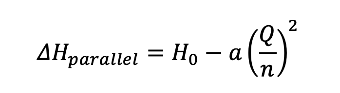
For identical pumps in series, the same flow rate Q passes through each pump in turn, and the heads add directly. If each pump produces ΔH = H₀ − aQ², then for n pumps in series:
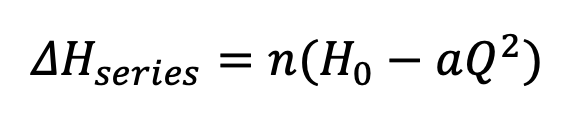
For two pumps, the combined head is 2(H₀ − aQ²), for three pumps it is 3(H₀ − aQ²), and so on.
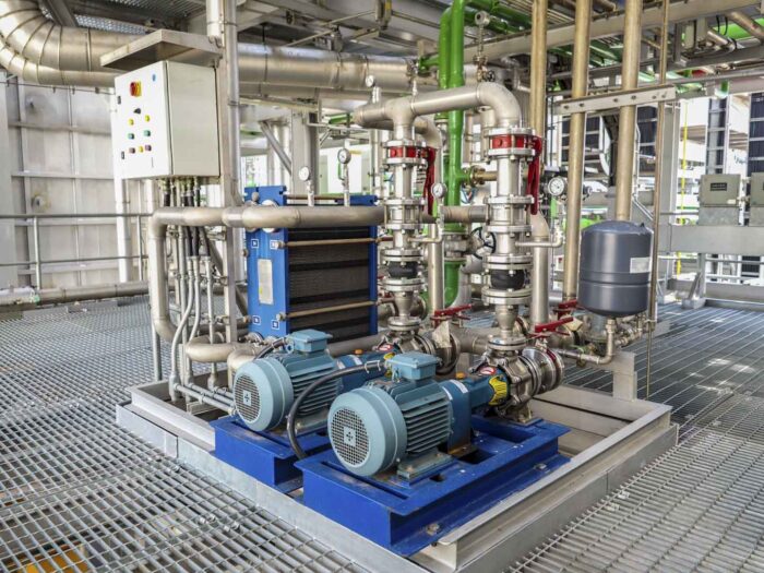
Figure 1 provides an illustration of a system with two identical pumps installed in series.
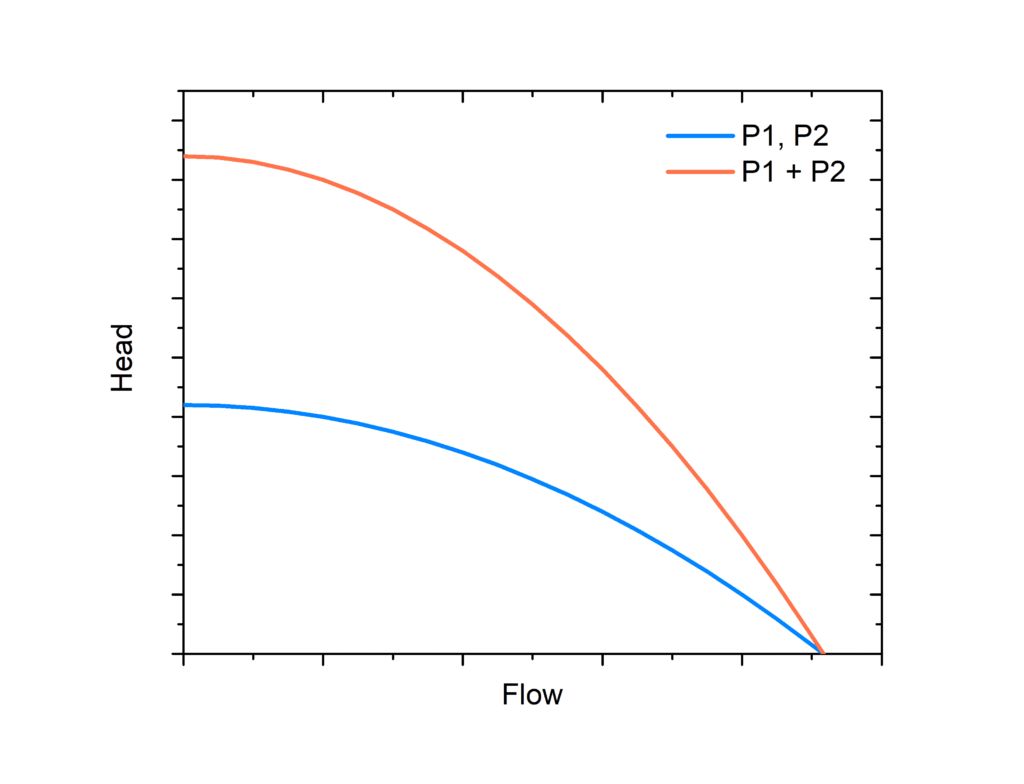
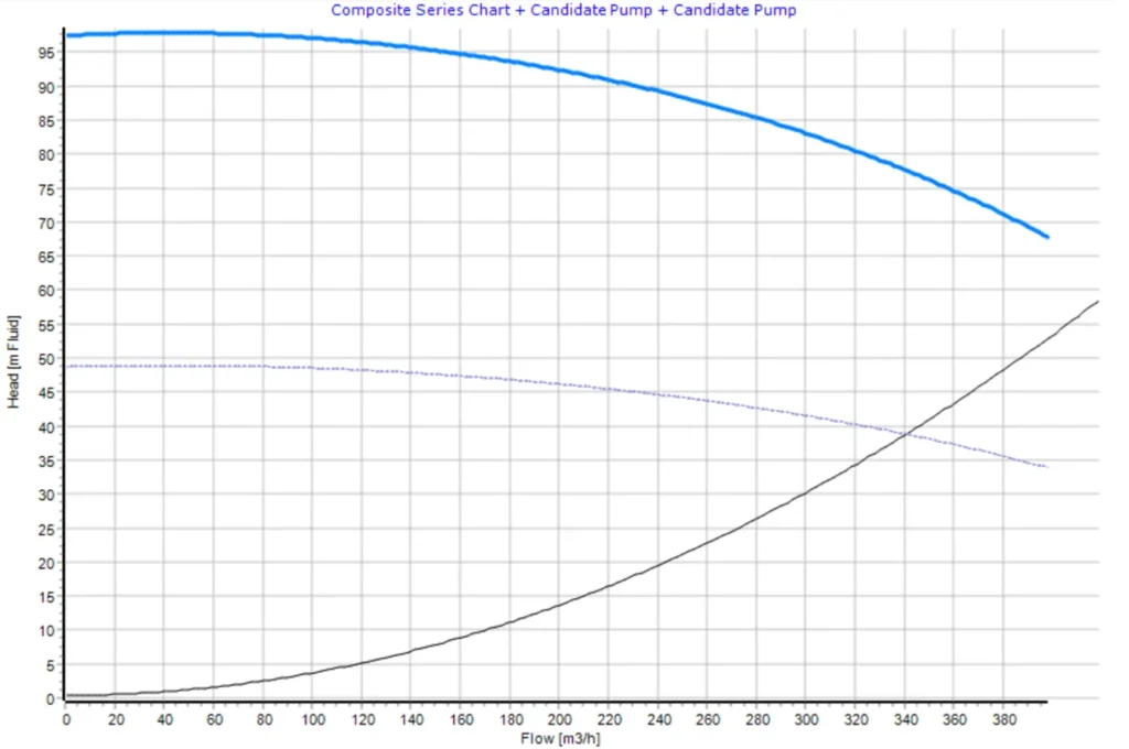
Figure 2 provides the composite pump chart for pumps in series plotted in FluidFlow.
Parallel Operation
For identical pumps in parallel, all pumps operate at the same head, and the total flow is shared equally between them. Each pump therefore carries a flow of Q/n, where Q is the total combined flow. Substituting into the individual pump curve gives the combined characteristic for n pumps in parallel:
For two pumps this becomes H₀ − a(Q/2)², and for three pumps H₀ − a(Q/3)². Notice that, unlike the series case, the correction factor appears inside the squared term, so the effect of adding parallel pumps on the curve shape is nonlinear.
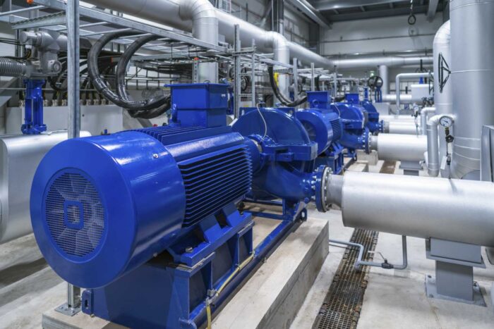
Figure 3 provides an illustration of a system with two identical pumps installed in parallel.
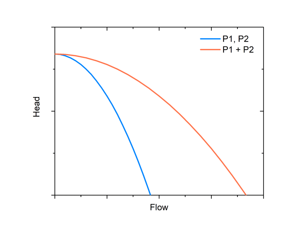
Figure 4 provides the composite pump chart for pumps in parallel plotted in FluidFlow.
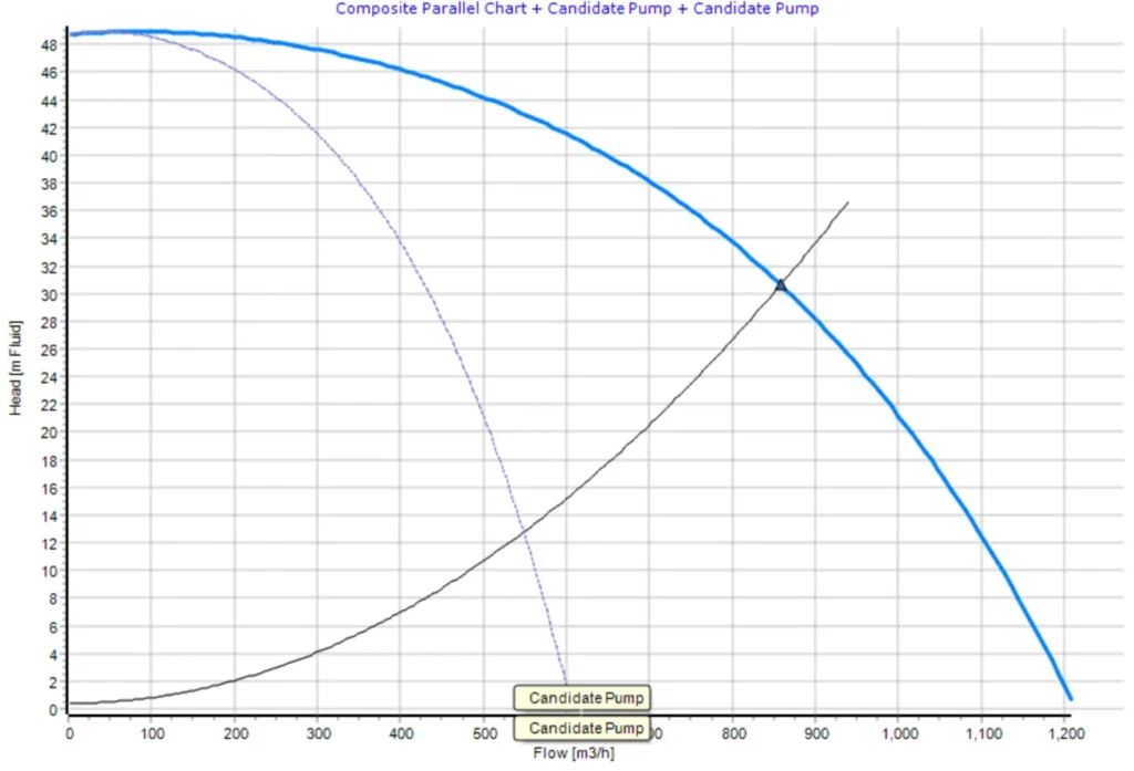
The actual operating point is where the combined pump curve intersects the system head curve. This intersection — not the nameplate rating of any individual pump — tells you what the system will actually deliver. Every pump in the configuration should operate near its Best Efficiency Point (BEP) at this intersection.
Series Configuration: What to Watch
When pumps are piped in series, the full combined discharge pressure acts on all downstream piping, fittings, flanges, and seals. Pressure ratings must account for the additive output of all pumps — for two pumps, this can be double the single-pump discharge pressure.
For non-identical pumps in series, a critical risk emerges: each pump has its own free-delivery flow rate (the flow at zero head). If the system operates beyond the free-delivery limit of the weaker pump, that pump ceases to contribute head and instead acts as a resistance. This can cause pump damage and reduce total system head. The solution is to install a bypass valve on each pump so it can be isolated when flow exceeds its capacity.
Parallel Configuration: What to Watch
The fundamental requirement for pumps in parallel is head matching — at the shared operating point, every pump must produce the same head. If the pumps have incompatible H-Q curves, the lower-head pump may be unable to discharge against the back-pressure imposed by the stronger pump, leading to flow reversal in that branch.
Check valves on each pump discharge are mandatory to prevent backflow through any pump that is shut down or cannot sustain the common system pressure. Isolation valves on each branch allow individual pumps to be taken in or out of service without shutting down the entire system.
For dissimilar pumps in parallel, the combined H-Q curve must be plotted carefully. If the smaller pump’s shutoff head is lower than the system head imposed by the larger pump, flow will reverse through the smaller pump’s branch — wasting power and risking damage.
Upset and Trip Conditions
Parallel Operation
When one pump in a parallel arrangement trips — whether from a motor overcurrent fault, loss of prime, or process interlock — the remaining pumps must immediately absorb the full system flow demand. Because the system head curve does not change instantaneously, the surviving pumps are forced to a new, higher operating point on their individual H-Q curves. Depending on how steeply the system curve rises with flow, this shift can push each remaining pump well beyond its rated capacity and toward the end of its performance envelope.
Operating near or beyond the pump’s run-out point carries serious consequences. At run-out, the pump is delivering maximum flow at minimum head; hydraulic efficiency drops sharply, shaft power demand peaks, and the motor is at risk of overcurrent trip — potentially cascading the original single-pump failure into a full system shutdown. Suction conditions also deteriorate: higher flow through the suction piping increases friction losses and reduces NPSHA, raising the risk of cavitation precisely when the system can least tolerate it. These scenarios must be modeled explicitly during design, not treated as unlikely edge cases. For each pump-out scenario, verify that the surviving pumps remain within their published safe operating range (typically 70–120% of BEP flow), that motor current stays within rated limits, and that NPSHA remains adequate at the increased flow rate. Where the analysis shows the operating point migrating too far toward run-out, corrective measures include sizing pumps with a steeper H-Q curve, adding flow-limiting orifices, or programming the control system to modulate pump speed via VFD when a unit trips rather than allowing the remaining pumps to accelerate unchecked.
Series Operation
When one pump in a series arrangement trips, the consequences are fundamentally different from the parallel case. Rather than the surviving pumps being forced to higher flow, they lose the head contribution of the failed unit — the total system head drops immediately. The operating point shifts along the system curve to a new intersection where the reduced combined head balances the system resistance. In a high-static-head system (long pipelines, significant elevation), this drop in available head may be enough to stall flow entirely or even cause flow reversal if the static head component exceeds what the remaining pumps can sustain alone.
The surviving pumps, now carrying the full pressure differential that was previously shared, may also see a change in their individual operating point. If the tripped pump’s casing remains in the flow path — as it will unless a bypass is opened — the impeller acts as a throttle, adding hydraulic resistance and further reducing system flow. This is the same risk described for non-identical pumps operating beyond the weaker pump’s free-delivery limit, now triggered dynamically by the trip event. The result is reduced throughput, elevated pressure drop across the idle casing, and potential for recirculation damage within the stopped pump if flow is forced back through it.
As with parallel systems, these scenarios must be evaluated at the design stage. For each pump-out case in a series train, verify that the remaining pumps do not move into a low-flow recirculation zone (below minimum continuous stable flow), that discharge pressures on the surviving pumps remain within casing and seal pressure ratings, and that the system does not experience uncontrolled flow reversal. Bypass valves around each pump — already recommended for non-identical series pumps — serve double duty here, allowing the tripped unit to be isolated quickly so the surviving pumps can re-establish a stable operating point.
NPSH: The Suction-Side Check That Gets Missed
Net Positive Suction Head Available (NPSHA) must be calculated for every pump in the configuration, at every expected flow rate. NPSHA decreases as flow increases because higher suction-line velocities create greater friction losses.
For parallel arrangements, adding pumps increases total system flow, which increases suction-side velocity and friction. Even if NPSHA was adequate for a single pump, it must be recalculated and verified for the full parallel flow condition. If NPSHA falls below the pump manufacturer’s stated NPSHR, cavitation will occur — producing noise, vibration, reduced efficiency, and progressive impeller damage.
When NPSHA is marginal, a suction booster pump upstream of the main pumps or a double-suction pump design can restore adequate margin.
Efficiency, Redundancy, and Controls
Combined efficiency: For identical pumps in series or parallel, the combined efficiency is approximately equal to the individual pump efficiency — but this is an approximation that holds best near the design point. In practice, even identical pumps will shift their individual operating points when combined onto a shared system curve, which can move each pump away from its Best Efficiency Point (BEP) and alter actual efficiency. For non-identical pumps, the combined efficiency curve must be derived separately, and careful analysis is required to ensure no individual pump is pushed into a low-efficiency, high-vibration, or damaging operating region — such as runout on the strong pump or near-shutoff on the weak one.
Redundancy analysis: The system must be modeled not just at full capacity but at partial load — one pump offline. With series pumps, removing one unit drops total head and shifts the operating point; if the failed unit blocks flow, the remaining pump risks cavitation or loss of prime and must be tripped immediately via protective controls. With parallel pumps, removing one unit reduces flow capacity at the same head, and the remaining pump must be checked to ensure it does not move into an unstable or overloaded region of its curve (runout). In both configurations, the remaining pumps must be verified to stay within safe operating limits, clear of cavitation, instability, and motor overload conditions.
Variable Frequency Drives (VFDs): VFDs allow pump speed to be varied continuously to match system demand, following the Affinity Laws (Q ∝ N, H ∝ N², BHP ∝ N³). The cubic relationship between power and speed means even modest speed reductions yield substantial energy savings — for example, reducing speed to 80% cuts power consumption to roughly 51% of its original value. This makes VFDs far more energy-efficient than throttling with a control valve, and especially valuable in parallel configurations where individual pumps can be ramped to track variable demand. However, VFDs are not lossless: they introduce 2–3% efficiency losses at full speed, and become less efficient as the load drops. At very low speeds, actual pump efficiency can fall meaningfully below what the Affinity Laws predict, so VFD losses should be accounted for in full life-cycle energy calculations.
Pressure instrumentation: Each pump requires suction and discharge pressure monitoring. The system requires flow measurement to verify that each pump operates at its intended duty point. Protective interlocks should prevent a pump from starting against a closed discharge valve, and alarms or trips should be configured for low suction pressure, high vibration, overtemperature, and motor overload. Automatic sequencing controls should start and stop pumps in the correct order based on system demand, and must ensure that no pump is left operating outside its safe hydraulic range under any staging combination.
How FluidFlow Supports Multi-Pump System Design
FluidFlow provides the tools to model and verify every aspect of a series or parallel pump configuration within a single steady-state network analysis:
- Pump curve entry: Import manufacturer H-Q curve data directly. FluidFlow calculates the operating point where the pump curve intersects the system head curve — no manual plotting required.
- Auto-sizing: FluidFlow can auto-size pumps, letting engineers evaluate whether a single larger pump or a multi-pump arrangement best meets the system demand.
- Composite pump curves: Visualize combined H-Q performance for series and parallel arrangements, confirming the actual operating point against each individual pump’s performance envelope.
- NPSH verification: FluidFlow calculates NPSHA at every pump inlet based on the full network geometry, fluid properties, and operating conditions — including the increased suction losses that occur when parallel pumps increase total flow.
FAQ
Q: Can I model non-identical pumps in series or parallel in FluidFlow?
A: Yes. Each pump can have its own manufacturer’s curve data. FluidFlow calculates the network operating point considering all pumps simultaneously, so mismatches in head or flow capacity are visible in the results.
Q: How do I check if my parallel pumps have adequate NPSH?
A: FluidFlow calculates NPSHA at each pump suction node based on the solved network conditions. Compare the reported NPSHA against the manufacturer’s NPSHR at the operating flow rate. If the margin is insufficient, adjust suction piping geometry, tank elevation, or consider a booster pump.
Q: Does FluidFlow account for the increased friction in suction piping when multiple pumps run in parallel?
A: Yes. The network solver determines the actual flow distribution across all branches, including suction headers, so increased flow from parallel operation is reflected in the friction calculations and the resulting NPSHA.
Q: Can I simulate one pump going offline in a multi-pump system?
A: Yes. Disable any pump component and recalculate. FluidFlow determines the new operating point for the remaining pumps, letting you verify that no pump moves outside its safe operating range.
Why does configuring your pumps correctly in series or parallel matter?
Getting pumps in series or parallel right is not just about matching a flow rate or hitting a head target — it is about verifying that every pump in the arrangement operates safely and efficiently under every anticipated condition, from full load to single-pump operation. The questions above — from combined curve construction through NPSH verification to redundancy analysis — are the checks that separate a system that runs reliably from one that cavitates, surges, or wastes energy from day one. FluidFlow lets you answer all of them in a single model, before steel is cut.
knowledge base
Ready to apply this in FluidFlow?
Set up parallel and series pumping configurations in FluidFlow — Modeling Pumps in Parallel & Series shows you how to plot the combined performance.